不记肯定会忘记QAQ,只敲简写然后敲tab也是可以的
enable
configure terminal
hostname R1
加密
enable password xxx # 设置用户执行密码
enable secret class # 设置特权执行密码
line console 0 #线路密码
(config-line)password cisco
(config-line)login
(config-line)exit
line vty 0 4 #加密密码设置
(config-line)password class
(config-line)login
(config-line)exit
service password-encrytion #加密纯文本密码
标语
banner motd $ ($是截止符号)
banner motd $ Authorized Access Only! $
保存配置
copy running-config startup-config
端口设置
interface f 0/0
(config-if)description Link to Lan 1
(config-if)ip address 192.168.10.1 255.255.255.0
(config-if)ipv6 address 2001:db8:acad:1::1/64 #IPV6
(config-if)no shutdown
(config-if)exit

#Serial口 作为DCE 要附加上
(config-if)clock rate 128000

#Loopback环回接口
interface loopback 0
(config-if)ip address 10.0.0.1 255.255.255.0
(config-if)exit
show
show ip interface brief
show ip ipv6 brief
show ip route
历史记录
terminal histroy size 200
show history
IPv6 地址解析不使用 ARP 进程,而是使用 ICMPv6 邻居请求和邻居通告消息。IPv6 到 MAC 地址的映射保存在一个类似于 ARP 缓存的表中,称为邻居缓存。
代码字母 D 用于标识通过 EIGRP 获知的路由。
“最后选用网关”是另一台路由器的ip地址
默认静态路由用作最后选用网关
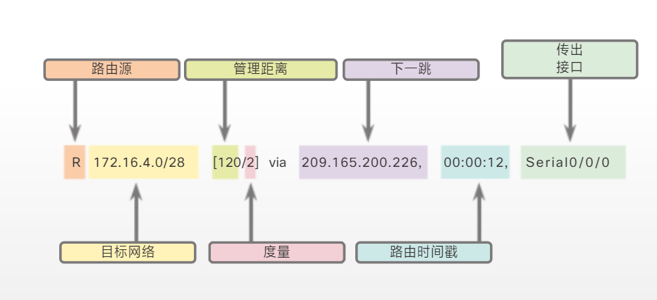
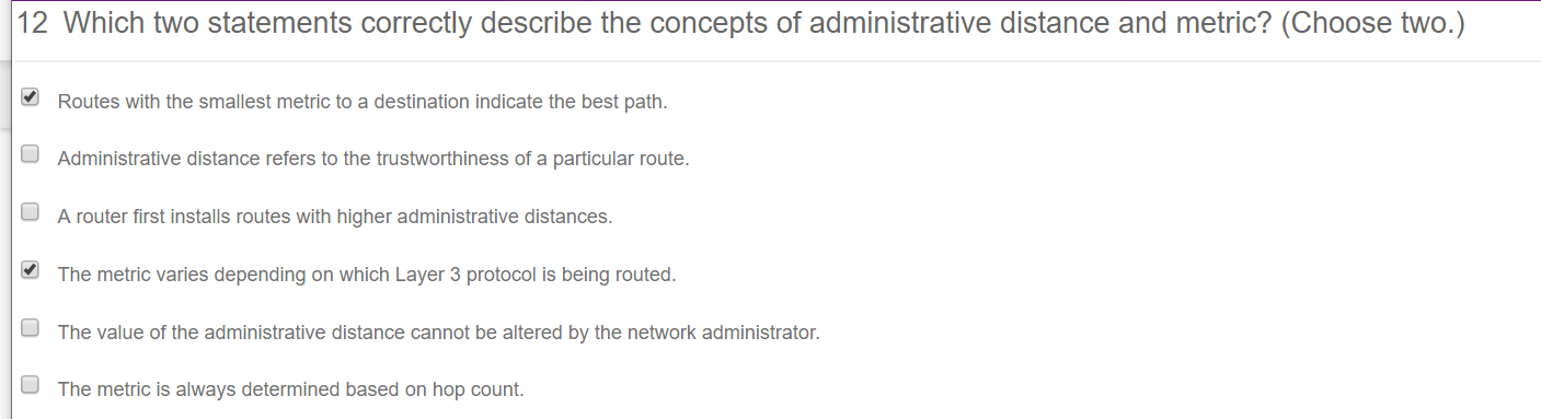
S 10.2.0.0 [1/0] via 172.16.2.2 中,方括号内的数字分别表示管理距离和度量。
ROM 包含在硬件模块上执行的诊断操作
默认静态路由的 IPv6 地址和前缀为 ::/0。这表示地址中的所有零和前缀长度零
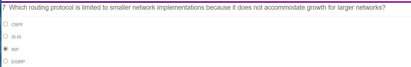
使用rip
router rip
network 网段
access-list
禁止访问
(config)#access-list 1 deny host 24.17.2.18
(config)#interface f0/0
(config-if)#ip access-group 1 in
(config)#access-list 1 permit any
permit anything from the subnet 24.17.2.0. Access-list 102 permit IP 24.17.2.0 0.0.0.15 any log
Router1(config)#access-list 102 permit ip 24.17.2.0 0.0.0.15 any log
allow telnet from 24.17.2.16
(config)#access-list 101 permit tcp 24.17.2.16 0.0.0.15 any eq telnet
1.1.3.5 Configuring IPv4 and IPv6 Interfaces
R1
cisco
enable
class
config t
interf g0/0
ip add 172.16.20.1 255.255.255.128
no shutdown
exit
interf g0/1
ip add 172.16.20.129 255.255.128
no shutdown
exit
R2
cisco
enable
class
config t
interf g0/0
ipv6 add 2001:DB8:C0DE:12::1/64
ipv6 address FE80::2 link-local
no shutdown
interf g0/1
ipv6 add 2001:DB8:C0DE:13::1/64
ipv6 address FE80::2 link-local
no shutdown
ex
测试
ping 172.16.20.1
ping 172.16.20.129
ping 64.100.1.10
ping 2001:DB8:C0DE:12::1
ping 2001:DB8:C0DE:13::1
ping 2001:DB8:100:1::A
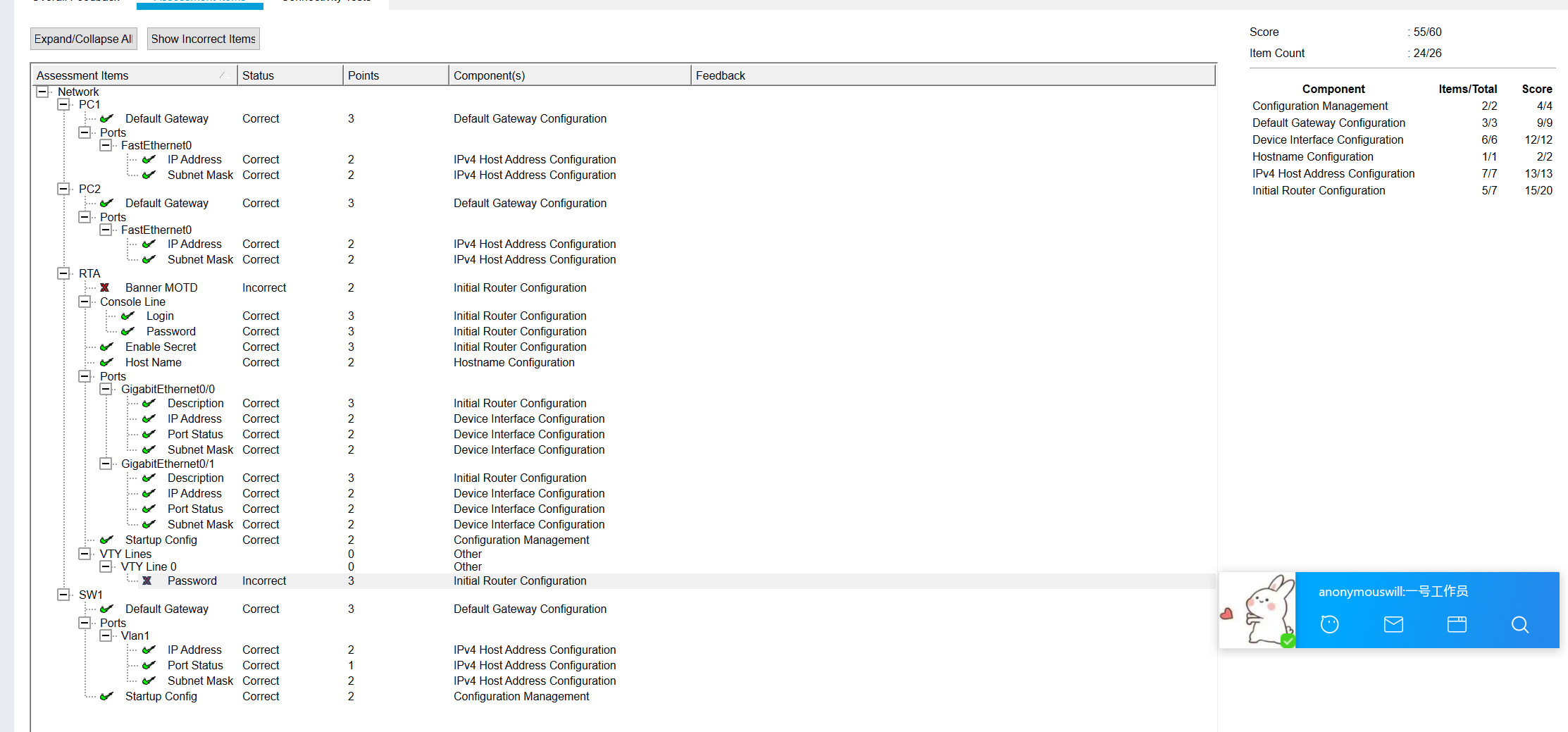
1.1.4.5 Configuring and Verifying a Small Network
RTA
enable secret class
line console 0
password cisco
login
exit
line vty 0
password class
login
exit
service password-encrytion

interf g0/0
ip add 10.10.10.1 255.255.255.0
des pc1
no shutdown
ex
interf g0/1
ip add 10.10.20.1 255.255.255.0
dec pc2
no shutdown
ex

copy running-config startup-config
SW1
int vlan1
ip add 10.10.10.2 255.255.255.0
no shutdown
ex
ip default-gateway 10.10.10.1
copy running-config startup-config
SW2
int vlan1
ip add 10.10.20.2 255.255.255.0
no shutdown
ex
ip default-gateway 10.10.20.1
1.3.2.5 Investigating Directly Connected Routes
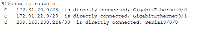
PC1可ping通PC2和PC3
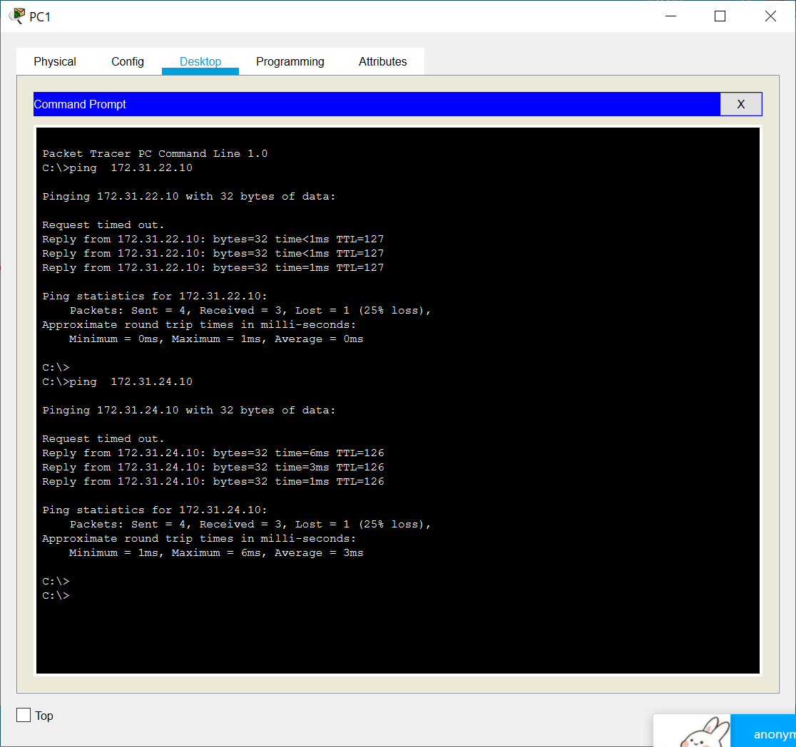
PC3可ping通PC4
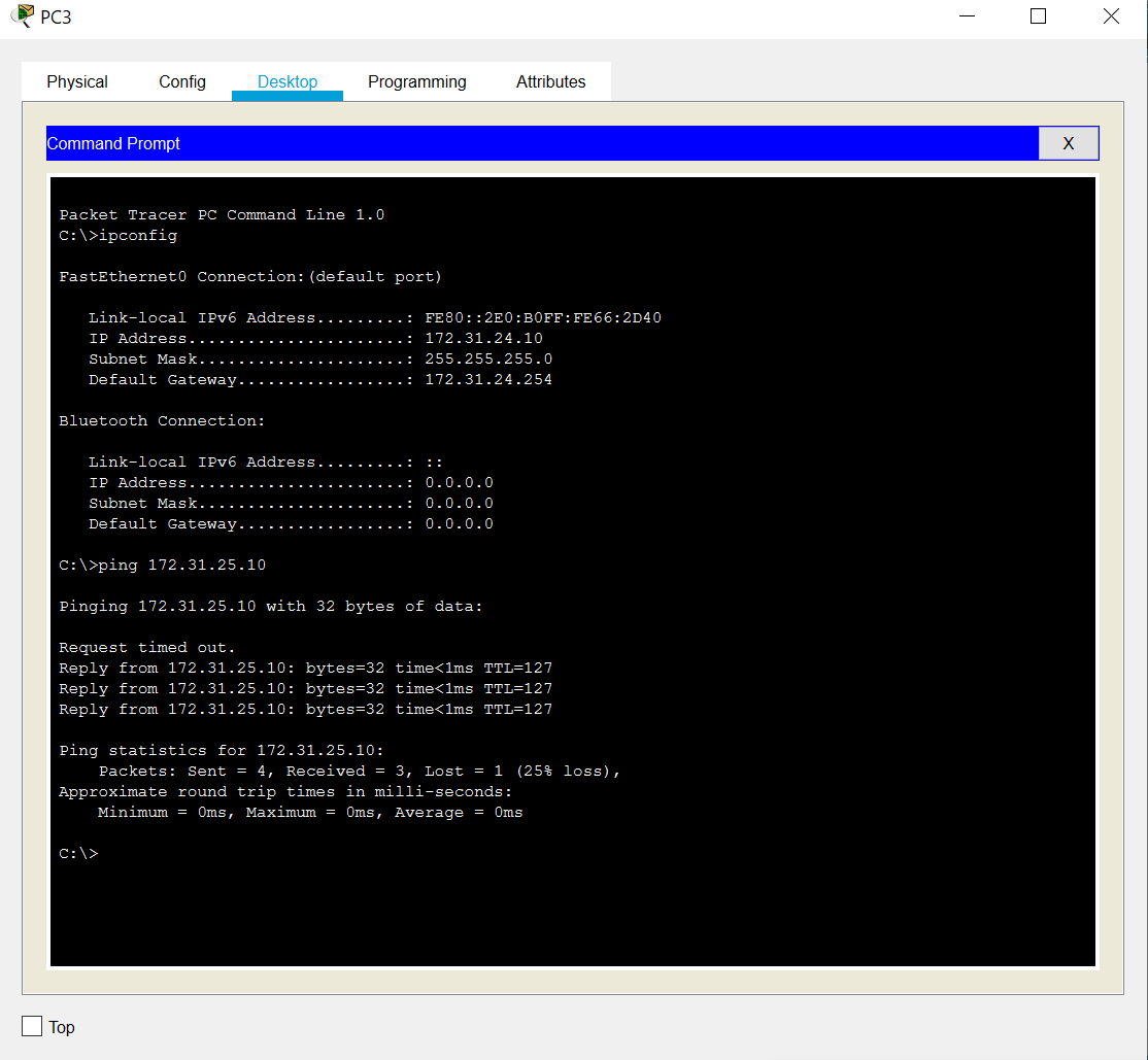
show ip route static 查看静态路由转发
v4可通,v6不通
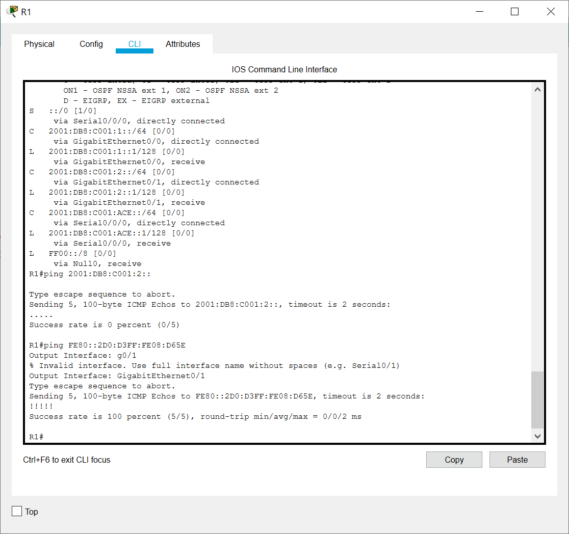
手动控制出口端口后又可通,并且查看路由表之后,发现没有FE的,都是2001的,说明是路由设置的问题
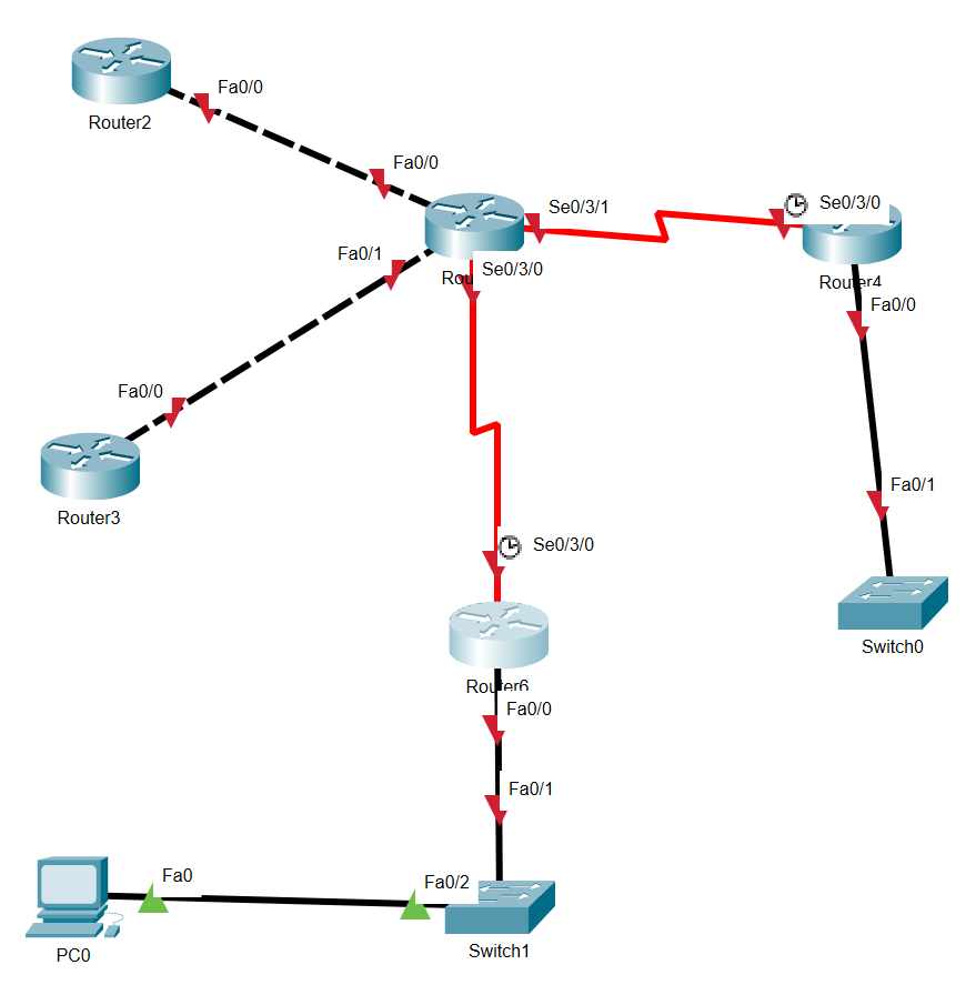
lab1&2.27笔记
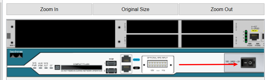
点这里关机,然后拖入模块

这个模块是有serial口的
config t
no ip domain-lookup
router> 是处于用户模式
router# 是处于特权模式 在用户界面使用enable启用
show hosts 显示分配了主机名的ip地址
设置远程登录
(config)line vty 0 4#虚拟终端
(config-line)password 123
(config-line)login #允许远程登录
enable secret 权限更高,可覆盖enable password
lab2
int s0/1
enable cdp
no shut
ex
cdp run
端口下 cdp enable
3/3笔记
浮动静态路由器:
- 备份动态路由协议已发现的路由
- 相比原动态路由协议,配置的管理距离更长
静态路由
ip route 网段 掩码 下一跳端口ip
ip route 172.16.1.0 255.255.255.0 172.16.2.2
ipv6 route 2001:DB8:ACAD:3::/64 2001:DB8:ACAD:4::2
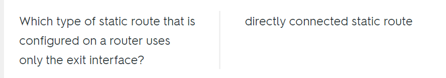
完全指定静态路由
ip route 网段 掩码 端口
R1(config)# ip route 192.168.2.0 255.255.255.0 GigabitEthernet 0/1
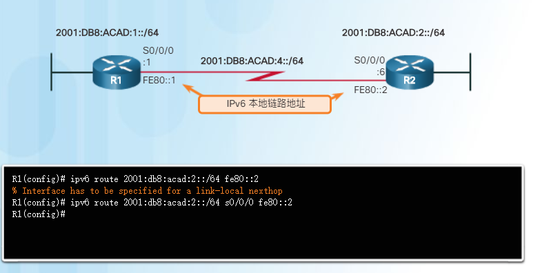
如果 IPv6 静态路由使用 IPv6 本地链路地址作为下一跳地址,则必须使用完全指定静态路由(包含送出接口)
默认静态路由
ip route 0.0.0.0 0.0.0.0 172.168.2.2
ipv6 route ::/0 2001:DB8:ACAD:4::2
!!! 浮动静态路由
ip route 0.0.0.0 0.0.0.0 172.16.2.2 # 默认静态路由
ipv6 route ::/0 ipv6_add
ip route 0.0.0.0 0.0.0.0 10.10.10.2 5 # 管理距离为5
ipv6 route ::/0 ipv6_add 5
2.2.4.4 Configuring IPv6 Static and Default Routes
R1
ipv6 unicast-routing
ipv6 route 2001:DB8:1:2::/64 2001:DB8:1:A001::2 # 递归静态路由
ipv6 route 2001:DB8:1:3::/64 2001:DB8:1:A001::2
ipv6 route 2001:DB8:1:A002::/64 2001:DB8:1:A001::2
R2
ipv6 unicast-routing
ipv6 route 2001:DB8:1:1::/64 2001:DB8:1:A001::1
ipv6 route 2001:DB8:1:3::/64 2001:DB8:1:A002::2
R3
ipv6 unicast-routing
IPV6 ROUTE ::/0 2001:DB8:1:A002::1 # 默认路由
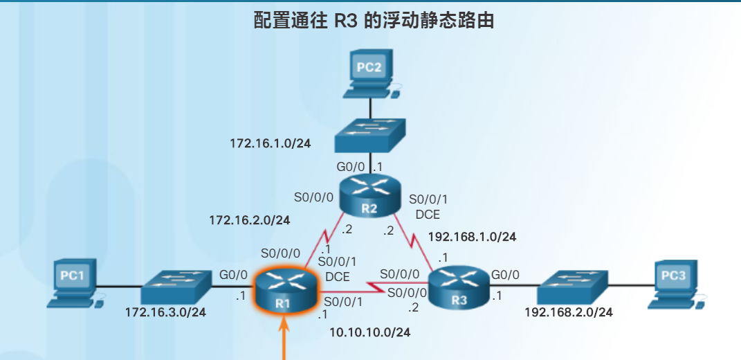
2.2.5.5 Configuring Floating Static Routes
Edge
ip route 0.0.0.0 0.0.0.0 s0/0/0
ip route 0.0.0.0 0.0.0.0 s0/0/1 5
ipv6 route ::/0 s0/0/0
ipv6 route ::/0 2001:DB8:A:2::1 5
2.3.2.3
R2
ip route 172.31.1.128 255.255.255.192 172.31.1.198
no ip route 172.31.1.128 255.255.255.192 172.31.1.194
ip route 172.31.1.0 255.255.255.128 172.31.1.194
no ip route 172.31.1.0 255.255.255.128 172.31.1.198
R3
ip route 172.31.1.0 255.255.255.128 172.31.1.197
lab 3&3/10
The Enable Password
The enable password controls access to privilege mode. This is a VERY important password because in privilege mode you can make configuration changes.
Krang(config)#enable password frodo
You can securely encrypt the enable password, by using the enable secret command.
Krang(config)#enable secret hobbits
If you have both passwords, the enable secret is the password used.
enable secret password 储存加密的密码,会覆盖enable password frodo
在端口上启用cdp run,本机路由器show cdp nei 看不见
而在别的路由上可以看见
如右边路由f0/0 只在端口上cdp run。左边端口和路由都cdp run了。左边show cdp nei能看见右边的端口,右边show cdp nei 看不见任何记录
Lab4
(config-if)description FastEthernet interface on Router 1
Lab5
clear arp
Lab 6
(config)#ip host California 195.42.36.10
show hosts
Lab 7
- Add RIP routing protocol to the router. What command does this?
Router2(config)#router rip

Router2(config-router)#
- Add the network(s) that Router 2 is directly connected to. What statements will do this?
Router2(config-router)#network 10.0.0.0
查看更新信息使用 debug ip rip 命令时,要用 terminal monitor 命令来接收debug 命令产生的输出。debug ip rip 会把更新信息发送给控制台会话。
Router#debug ip rip
RIP protocol debugging is on
Router#terminal monitor
接下来就是输出的更新信息,但是它会不断的出来,所以要停止它就得输入 un all 或 undebug all 或 no debug ip rip 即可停止信息的输出
Router#un all
3.17&Lab 9
路由器连接到server,并且server开启tftp时候
Tampa# copy running-config tftp
Address or name of remote host []?192.168.1.2
储存的文件名:Tampa_config
Lab10待补-不熟!!!
lab13
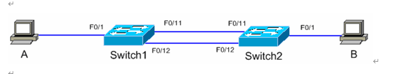
**交换机之间的线用copper cross-over **
sw1:
int f0/3
switchport mode access
switchport access vlan 2
int f0/4
switchport mode access
switchport access vlan 3
int f0/2
switchport mode trunk
int f0/1
switchport mode trunk

sw2:
int f0/2
switchport mode access
switchport access vlan 2
int f0/3
switchport mode access
switchport access vlan 3
int f0/1
switchport mode trunk

router:
int f0/0.1
encapsulation dot1Q 2
ip add 192.168.1.254 255.255.255.0
no shut
int f0/0.2
encapsulation dot1Q 3
ip add 192.168.2.254 255.255.255.0
no shut
int f0/0
no shut
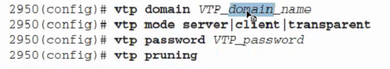
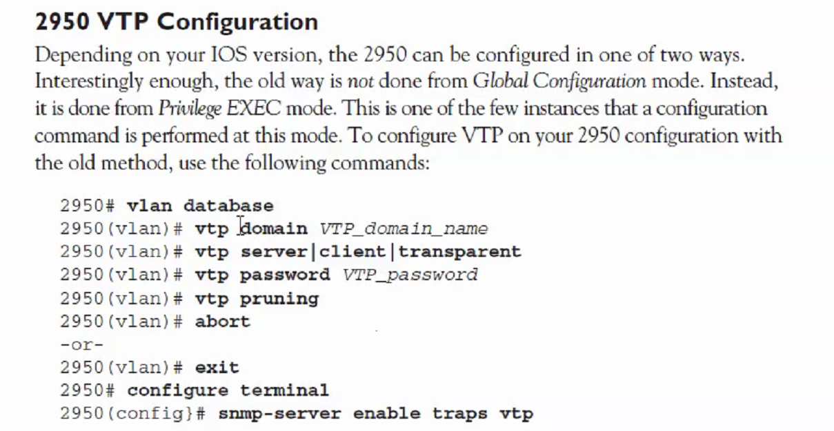
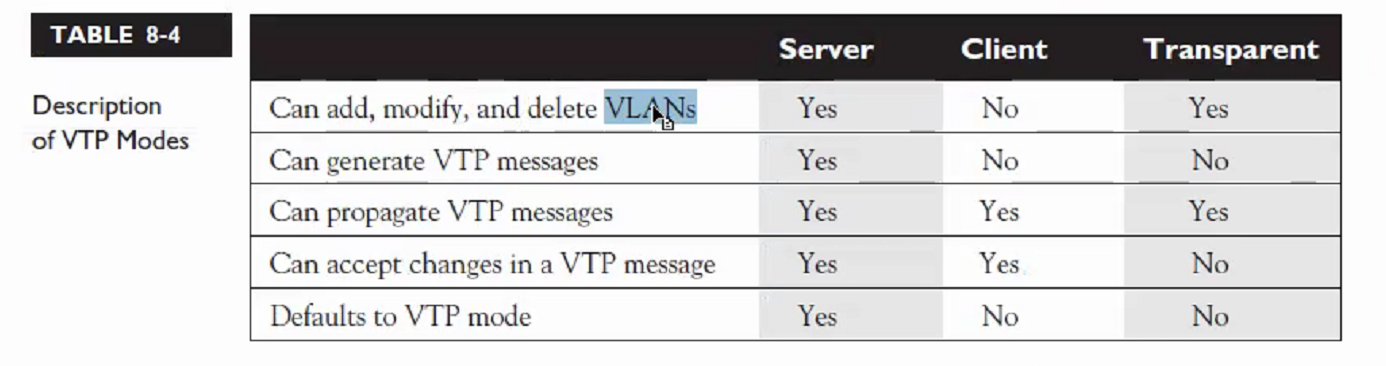
VTP
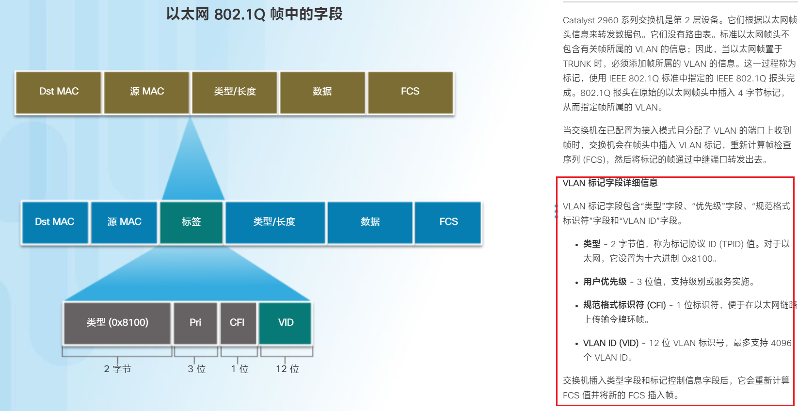
VLAN 中继协议 (VTP) 的信息。VTP 可简化交换网络中的管理。在一台 VTP 服务器上配置新的 VLAN 时,该 VLAN 将通过域中的所有交换机进行分发。这样可以减少在各处配置相同 VLAN 的需求。VTP 是一种 Cisco 专有协议
3. 在switch1合适的配置模式下设置如下命令。
vtp mode server
vtp domain cisco
vlan 10
vlan 100
在switch2合适的配置模式下设置如下命令。
vtp client
vtp domain cisco
Lab 14
EIGRP
Router(config)#router eigrp ?
  <1-65535>  Autonomous system number
R2(config-router)#network 12.1.1.0 0.0.0.255
R2(config-router)#network 2.2.0.0 255.255.0.0 (正/反掩码皆可)
RIP
Router(config)#router rip
version 2
network 120.10.10.0
OSPF
Router(config)#router ospf ?
  <1-65535>  Process ID
network 120.10.10.0 0.0.0.252 area ?
  area  Set the OSPF area ID
lab 15
NAT,详见link
端口多路复用
Access-list 12 permit 192.168.101.0 0.0.0.255
ip nat inside source list 12 interface serial 1/0 overload
NAT pool
interface loopback 0
ip address 192.168.200.1 255.255.255.0
!
ip nat pool goodpool 192.168.200.2 192.168.200.101 netmask 255.255.255.0
access-list 10 permit 192.168.101.0 0.0.0.255
ip nat inside source list 10 pool goodpool
Lab 16
interface fastethernet 0/11
switchport mode trunk
interface fastethernet 0/11
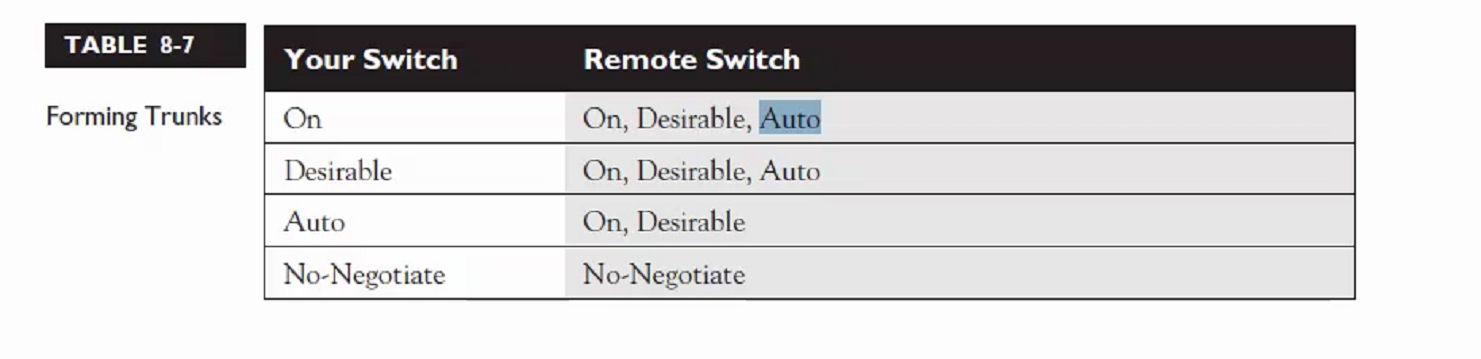
switchport mode dynamic desirable
3/26
3/31
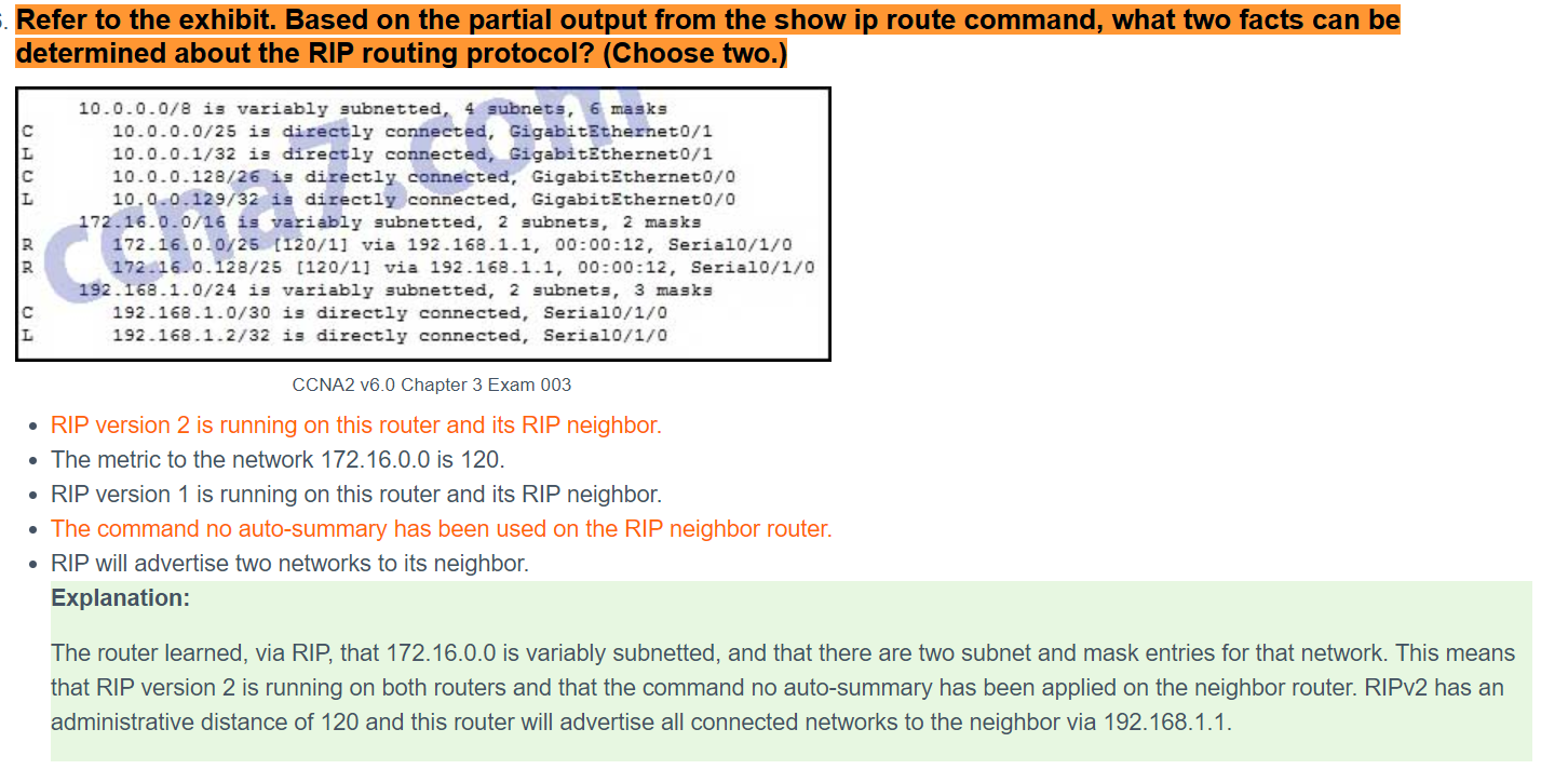
RIPv2自动汇总
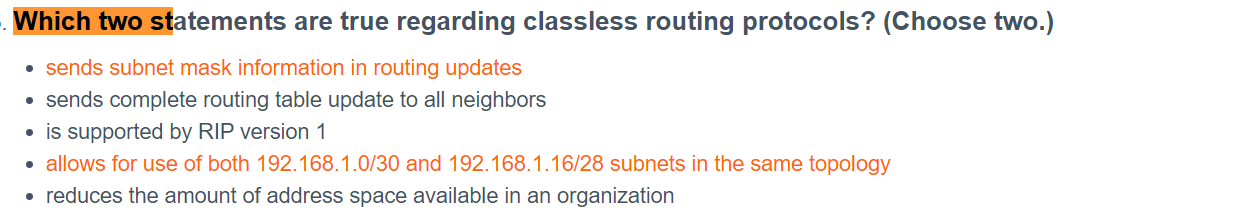
使用 no auto-summary 路由器配置模式命令,修改默认 RIPv2 自动汇总行为。当使用 RIPv1 时,此命令无效。当已禁用自动汇总时,RIPv2 不会再将网络汇总到其在边界路由器上的有类地址。
配置被动接口
默认情况下,将 RIP 更新从所有启用 RIP 的接口发出。使用 passive-interface 路由器配置命令阻止通过路由器接口传输路由更新,但是仍然允许将该网络通告至其他路由器。该命令会停止指定接口的路由更新。但是,从其他接口发出的路由更新中仍通告指定接口所属的网络。可以使用 passive-interface default 命令将所有接口设为被动。不能设为被动的接口可以使用 no passive-interface 命令重新启用。
router rip
passive-interface g0/0
end
传播默认路由
边缘路由器必须配置:
使用 ip route 0.0.0.0 0.0.0.0 next_ip 命令的默认静态路由。
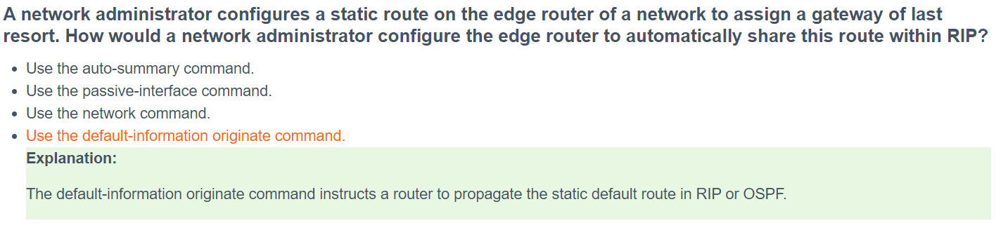
default-information originate 路由器配置命令。这会指导 R1 通过在 RIP 更新中传播静态默认路由来产生默认信息。
在一个单出口网络内启用RIP协议,在网络出口处的路由器需要向RIP域内传播一条默认路由,这样,域内的路由器就可以通过默认路由访问外部网络。下面我们就用试验来模拟这个环境。到目前为止;通过RIP传递默认路由共有5种方法。 1 default-information 2 手工写一条默认路由(到NULL0) 然后重分布到RIP中 3 手工写一条默认路由(到NULL0)在进程中宣告 4 ip default-network 5在接口汇总0.0.0.0/0到NULL0的路由
3.2.1.8 Troubleshooting Static Routes
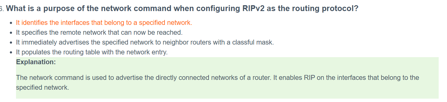
RIP配置的时候宣告自己所在的网段即可
R1
ip route 0.0.0.0 0.0.0.0 s0/0/1
router rip
version 2
network 192.168.1.0
network 192.168.2.0
no auto-summary
passive-interface s0/0/1
default-information originate # 通告配置的默认路由

R2
router rip
version 2
network 192.168.2.0
network 192.168.3.0
network 192.168.4.0
no auto-summary
passive-interface g0/0

R3
router rip
version 2
network 192.168.4.0
network 192.168.5.0
no auto-summary
passive-interface g0/0
4/14&5.2.1.4 Configuring SSH !!!!
==生成树协议学习一下==
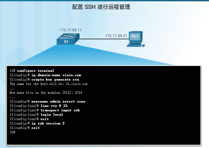
copy running-config start
service password-encryption

ip domain-name netacad.pka
crypto key generate rsa
1024
username administrator secret cisco
line vty 0 15
transport input ssh
login local
no password #删除密码
exit
ip ssh version 2
exit
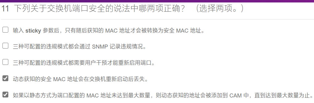
5.2.2.7 Configuring Switch Port Security !!!!
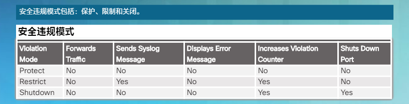
端口安全违规的默认模式为关闭端口
int f0/0
switchport mode access # 设为接入
switchport port-security # 启用动态端口安全
switchport port-security maximum 10 # 设置端口允许安全地址的最大数量
switchport port-security mac-address sticky #启用粘性获取,保护端口安全,以便动态获取设备的 MAC 地址并将其添加到运行配置
switchport port-security violation restrict #保护接口,使其在出现违规时发出通知,但不禁用端口
interface range fastEthernet0/3 - 24 # 从3到24端口全部关闭
安全违规模式-Protect\Restrict\Shutdown
5.3.1.2 Skills Integration Challenge
host S1
line console 0
password cisco
login
exit
enable secrect class
service password-encryption

int vlan1
ip add 10.10.10.2 255.255.255.0
no shut

ip domain-name cisco.com
crypto key generate rsa
1024
username admin secret ccna
line vty 0 15
transport input ssh
login local
exit
ip ssh version 2
exit

int f0/1
switchport mode access
switchport port-security
switchport port-security maximum 2
switchport port-security mac-address sticky #启用粘性获取,保护端口安全,以便动态获取设备的 MAC 地址并将其添加到运行配置
switchport port-security violation shutdown #保护接口,使其在出现违规时发出通知,禁用端口
int f0/2
switchport mode access
switchport port-security
switchport port-security maximum 2
switchport port-security mac-address sticky
switchport port-security violation shutdown
interface range fastEthernet0/3 - 24 # 从3到24端口全部关闭
shutdown
interface range g0/1 - 2 #
shutdown
a5.1.2.12 Determining the DR and BDR
show ip ospf interface

#RA:
int g0/0
ip ospf priority 200

#RB:
int g0/0
ip ospf priority 100

#RC:
int g0/0
ip ospf priority 1
a5.1.3.5 Propagating a Default Route in OSPFv2
#R2
ip route 0.0.0.0 0.0.0.0 s0/1/0
router ospf 1

#R1
router ospf 1

#R3
router ospf 1
a5.1.5.7 Configuring OSPF Advanced Features
#R1
int s0/0/0
ip ospf hello-interval 15 #调整计时器
ip ospf dead-interval 60

bandwidth 64 #调整带宽

router ospf 1
area 0 authentication message-digest #OSPF身份验证
interface serial 0/0/0
ip ospf message-digest-key 1 md5 R1-R2

interface serial 0/0/1
ip ospf message-digest-key 1 md5 R1-R3

#R2
int s0/0/0
ip ospf hello-interval 15
ip ospf dead-interval 60

router ospf 1
area 0 authentication message-digest
interface serial 0/0/0
ip ospf message-digest-key 1 md5 R1-R2

interface serial 0/0/1
ip ospf message-digest-key 1 md5 R2-R3

#R3
router ospf 1
area 0 authentication message-digest

interface serial 0/0/0
ip ospf message-digest-key 1 md5 R1-R3

interface serial 0/0/1
ip ospf message-digest-key 1 md5 R2-R3
a5.2.1.4 Configuring Static NAT no yet
a5.2.2.3 OSPFv2排错
a6.2.3.6 Configuring Multiarea OSPFv2
#R1
router ospf 1
router-id 1.1.1.1
network 10.1.1.0 0.0.0.255 area 1
network 10.1.2.0 0.0.0.255 area 1
network 192.168.10.0 0.0.0.3 area 0

#R2
router ospf 1
network 10.2.1.0 0.0.0.255 area 0
network 192.168.10.0 0.0.0.3 area 0
network 192.168.10.4 0.0.0.3 area 0

#R2
router ospf 1
network 192.168.1.0 0.0.0.255 area 2
network 192.168.2.0 0.0.0.255 area 2
network 192.168.10.4 0.0.0.3 area 0
a7.2.2.4 Configuring Basic EIGRP with IPv4
#R1:
router eigrp 1
network 172.16.1.0 0.0.0.255
network 172.16.3.0 0.0.0.3
network 192.168.10.4 0.0.0.3
passive-interface g0/0
no-autosummary

#R2:
router eigrp 1
network 172.16.2.0 0.0.0.255
network 172.16.3.0 0.0.0.3
network 192.168.10.8 0.0.0.3
passive-interface g0/0
no-autosummary

#R3:
router eigrp 1
network 192.168.1.0 0.0.0.255
network 192.168.10.4 0.0.0.3
network 192.168.10.8 0.0.0.3
passive-interface g0/0
no-autosummary
4/23
switchport port-security mac-address {mac_address} # 静态配置
4/28
show vtp status
switchport mode dynamic
isl:思科专有
encapsulation dotlQ {num}
4/30
存储转发
完全存下来、校验之后再转发
直通
知道目的mac就开始转发
5/12
查看当前ios文件设置
show boot
dir 命令可用于查看指定目录中的文件列表
dir flash
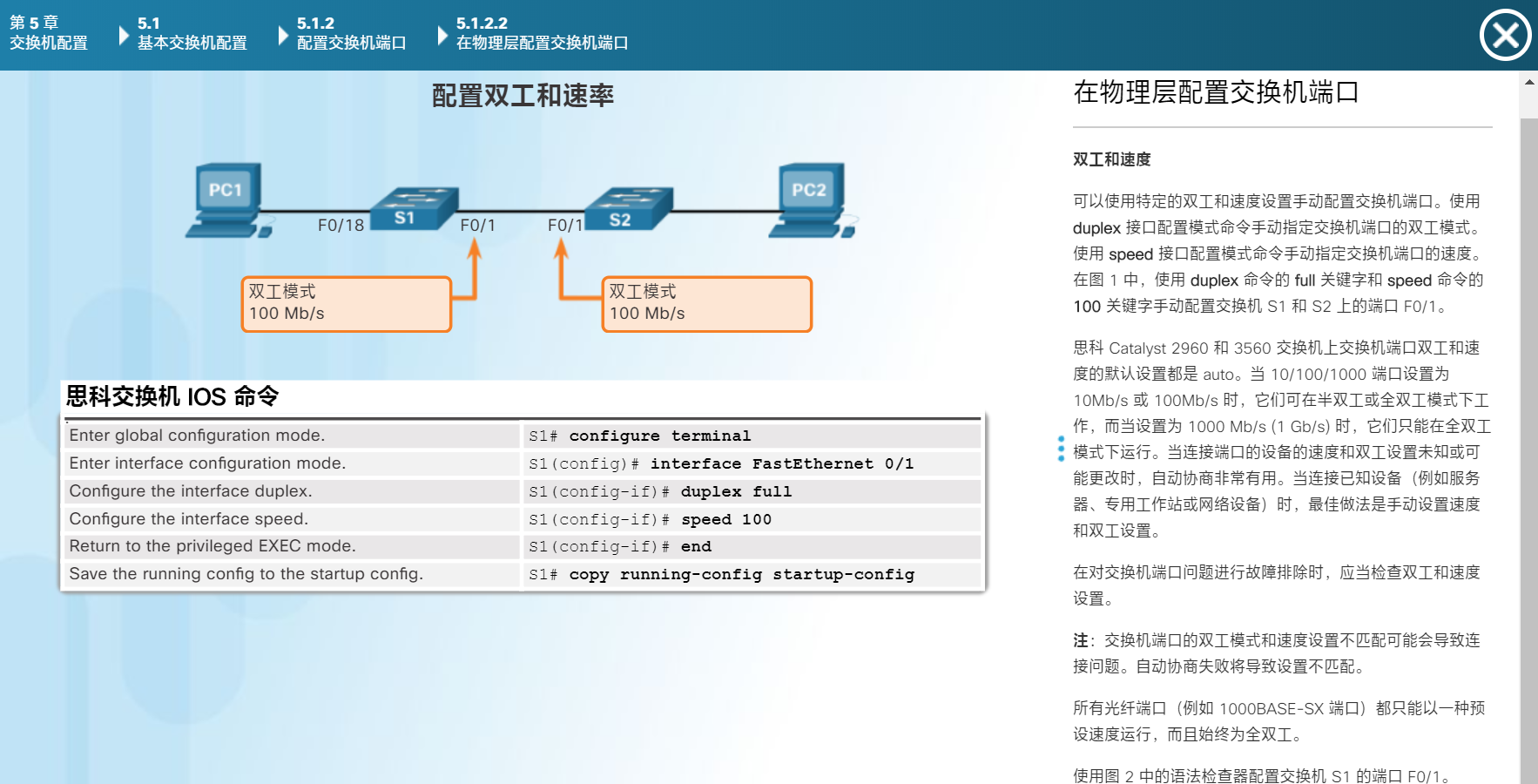
配置双工和速率
intferface f0/1
duplex full //自动协商双工
speed 100
end
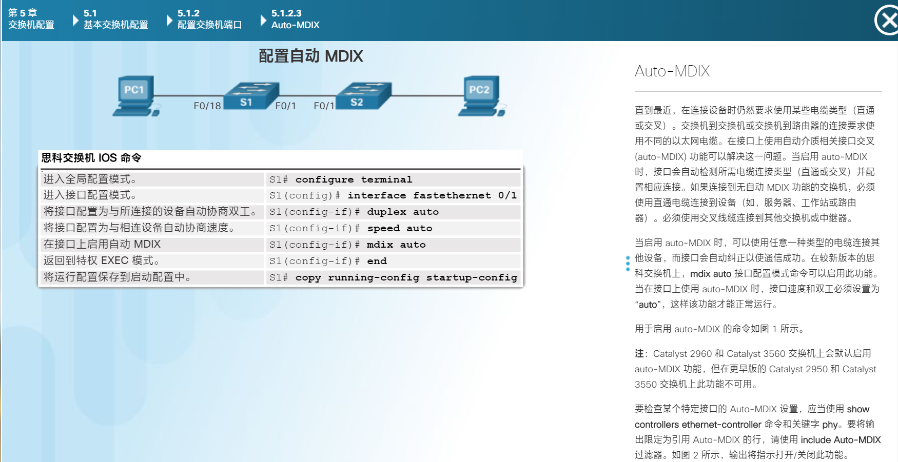
Auto-MDIX
交换机到交换机或交换机到路由器的连接要求使用不同的以太网电缆。在接口上使用自动介质相关接口交叉 (auto-MDIX) 功能可以解决这一问题。当启用 auto-MDIX 时,接口会自动检测所需电缆连接类型(直通或交叉)并配置相应连接。如果连接到无自动 MDIX 功能的交换机,必须使用直通电缆连接到设备(如,服务器、工作站或路由器)。必须使用交叉线缆连接到其他交换机或中继器。
int f0/1
duplex auto
speed auto //自动协商速度
mdix auto //启动mdix
end
6.1.1.2 Vlan的优势
VLAN 主要有以下优点:
安全 - 含有敏感数据的用户组可与网络的其余部分隔离,从而降低泄露机密信息的可能性。如图所示,教师计算机位于 VLAN 10 上,与学生和访客数据流量完全独立。
成本降低 - 成本高昂的网络升级需求减少,现有带宽和上行链路的利用率更高,因此可节约成本。
性能提高 - 将第 2 层平面网络划分为多个逻辑工作组(广播域)可以减少网络上不必要的流量并提高性能。
减小广播域大小 - 将网络划分为多个 VLAN 可减少广播域中的设备数量。如图所示,该网络中有六台计算机,但有三个广播域:Faculty、Student 和 Guest。
提高 IT 员工效率 - VLAN 为管理网络带来了方便,因为有相似网络需求的用户将共享同一个 VLAN。当您为特定 VLAN 设置新的交换机时,之前为该 VLAN 配置的所有策略和程序均会在分配新端口后应用到端口上。另外,通过为 VLAN 设置一个适当的名称,IT 员工很容易就知道该 VLAN 的功能。在图中,为了便于识别,我们将 VLAN 10 命名为“Faculty”,将 VLAN 20 命名为“Student”,将 VLAN 30 命名为“Guest”。
简化项目管理和应用管理 - VLAN 将用户和网络设备聚合到一起,以支持商业需求或地域上的需求。通过划分职能,可以让管理项目或使用专业应用更加轻松;此类应用程序的一个例子是教师的电子学习开发平台。
有vlan,广播帧只从已配置,属于同一vlan的端口转发出去。
5/19
vlan的类型
在图中,运行默认配置的交换机上发出 show vlan brief 命令。默认情况下,所有端口都分配给 VLAN 1。
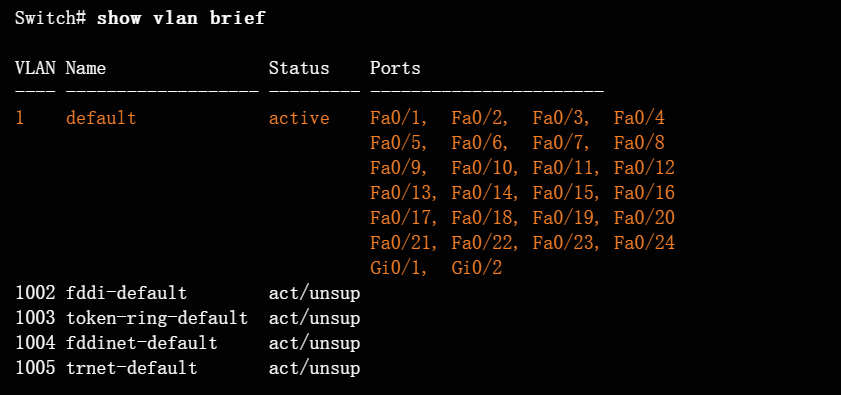
所有端口当前已分配给默认 VLAN 1。没有明确指定本征 VLAN,其他 VLAN 都不处于活动状态;因此网络的本征 VLAN 与管理 VLAN 相同。这将导致安全风险
6.1.2.1 Vlan中继
VLAN TRUNK 允许在交换机之间传播所有 VLAN 流量,这样位于同一 VLAN 但连接到不同交换机的设备便可以通信,不需要路由器的干预。VLAN TRUNK 不属于具体的 VLAN,而是作为多个 VLAN 中交换机与路由器之间的管道。
6.1.2.3 标记以太网帧以便识别VLAN
6.2.1.2 创建vlan
configure terminal
vlan vlan-id
name vlan-name
end

show vlan brief
show vlan
5/21
6.2.1.3 端口分配到vlan
configure terminal
interface interface_id
switchport mode access
switchport access vlan vlan_id
end
注:使用 interface range 命令可同时配置多个接口。
6.2.1.4 删除vlan分配
configure terminal
interface f0/18
no switchport access vlan
end
6.2.1.5 删除
no vlan vlan_id 删除vlan
6.2.1.7
S1(config)#vlan 10
S1(config-vlan)#name Faculty/Staff
S1(config-vlan)#exit
S1(config)#vlan 20
S1(config-vlan)#name Students
S1(config-vlan)#ex
S1(config)#vlan 30
S1(config-vlan)#name Guest(Default)
S1(config-vlan)#ex
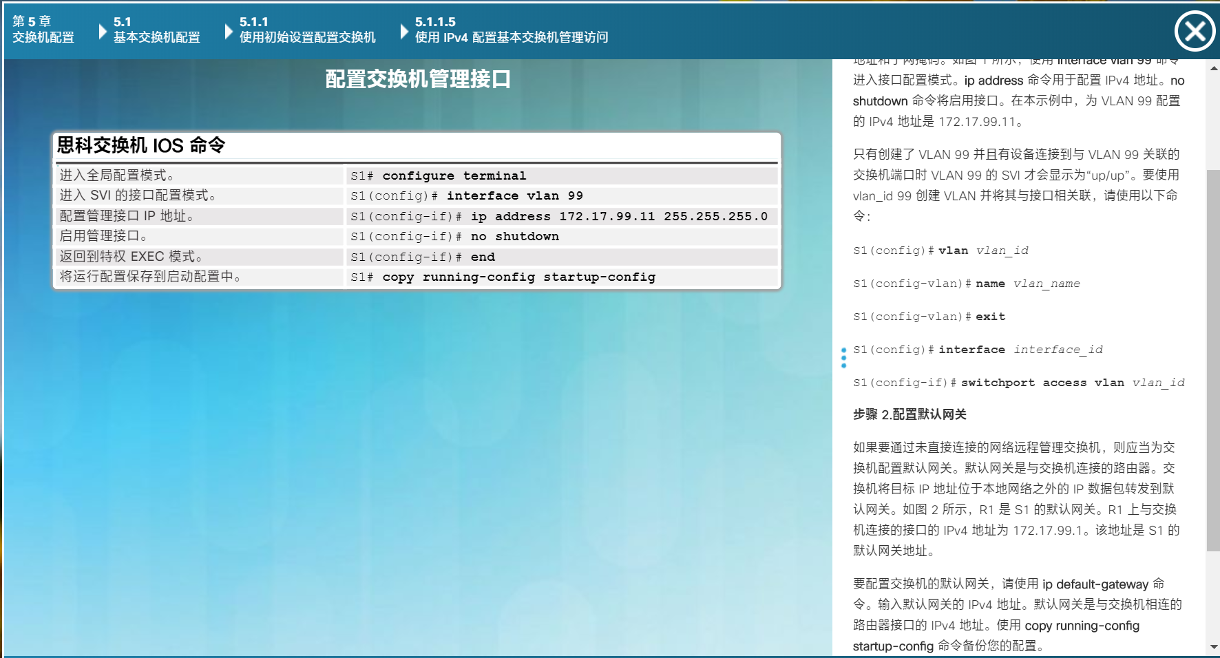
S1(config)#vlan 99
S1(config-vlan)#name Management&Native
S1(config-vlan)#ex
int g0/1
switchport mode trunk
int g0/2
switchport mode trunk
S2(config)#vlan 10
S2(config-vlan)#name Faculty/Staff
S2(config-vlan)#vlan 20
S2(config-vlan)#name Students
S2(config-vlan)#vlan 30
S2(config-vlan)#name Guest(Default)
S2(config-vlan)#vlan 99
S2(config-vlan)#name Management&Native
S2(config-vlan)#int f0/11
S2(config-if)#switchport mode access
S2(config-if)#switchport access vlan 10
S2(config-if)#int f0/18
S2(config-if)#switchport mode access
S2(config-if)#switchport access vlan 20
S2(config-if)#int f0/6
S2(config-if)#switchport mode access
S2(config-if)#switchport access vlan 30
S2(config)#int g0/1
S2(config-if)#sw mod tr
S2(config-if)#sw mod trunk
S3(config)#vlan 10
S3(config-vlan)#name Faculty/Staff
S3(config-vlan)#
S3(config-vlan)#vlan 20
S3(config-vlan)#name Students
S3(config-vlan)#vlan 30
S3(config-vlan)#name Guest(Default)
S3(config-vlan)#vlan 99
S3(config-vlan)#name Management&Native
S3(config-vlan)#ex
S3(config)#int f0/11
S3(config-if)#sw mod ac
S3(config-if)#sw mod access
S3(config-if)#sw acc vlan 10
S3(config-if)#int f0/18
S3(config-if)#sw mod access
S3(config-if)#sw acc vlan 20
S3(config-if)#int f0/6
S3(config-if)#sw mod access
S3(config-if)#sw acc vlan 30
S3(config-if)#int g0/2
S3(config-if)#sw mode tr
##5/25
6.2.2.2 原生vlan
switchport mode trunk
switchport trunk native vlan vlan_id # 指定vlan给没标记的帧 原生vlan
switchport trunk allowed vlan vlan-list # 指定可以通过的vlan清单

no switchport trunk allowed vlan #设为允许所有
no switchport trunk native vlan #将原生vlan重置为默认
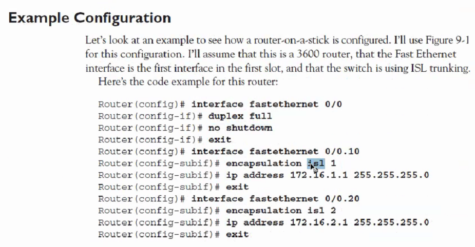
6.3.3.3 单臂路由器
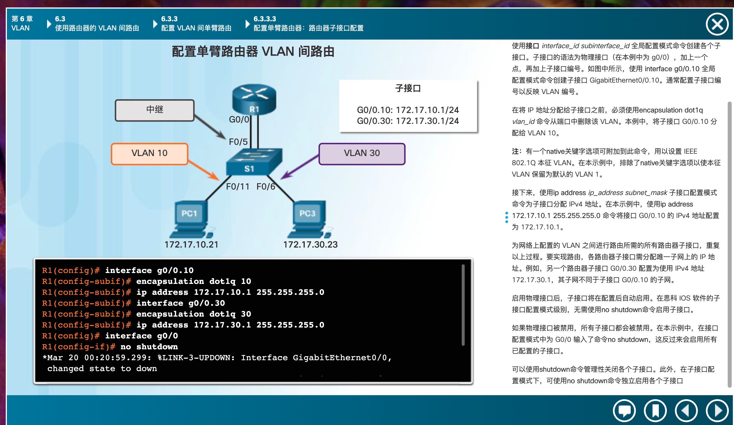
interface g0/0.10
encapsulation dotlq 10
ip add
interface g0/0.30
encapsulation dotlq 30

int g0/0
no shutdown
6.2.2.4
S2S3先按表分配

S1

int g0/1
sw mo tr
sw tr native vlan 99

int g0/2
sw mo tr
sw tr native vlan 99

S2

int g0/1
sw mo tr
sw tr native vlan 99

S3

int g0/2
sw mo tr
sw tr native vlan 99
6.2.3.7
S3有bug,pc5接在f0/17上
S2(config)#int f0/11
S2(config-if)#no sw ac vlan 30
S2(config-if)#sw ac vlan 10
S2(config-if)#int g0/1
S2(config-if)#sw mo t
S2(config-if)#sw mo trunk

S3(config)#int f0/6
S3(config-if)#no sw ac vlan 20
S3(config-if)#sw ac vla 30
S3(config)#int f0/17
S3(config-if)#sw ac vla 20


PC6的ip改成172.17.30.26
6.2.3.8
排错,先放过
6.3.3.6
S1(config)#vlan 10
S1(config-vlan)#ex
S1(config)#vlan 30
S1(config-vlan)#int f0/11
S1(config-if)#sw m ac
S1(config-if)#sw ac vlan 10
S1(config-if)#int f0/6
S1(config-if)#sw m ac
S1(config-if)#sw ac vlan 30
S1(config-if)#int g0/1
S1(config-if)#sw m trunk

R1(config-if)#int g0/0.10
R1(config-subif)#encapsulation dot1Q 10
R1(config-subif)#ip add 172.17.10.1 255.255.255.0
R1(config-subif)#int g0/0.30
R1(config-subif)#encapsulation dot1Q 30
R1(config-subif)#ip add 172.17.30.1 255.255.255.0
R1(config-subif)#int g0/0
R1(config-if)#no shut
6.3.3.8
R1(config)#int g0/0
R1(config-if)#ip ad  172.17.25.2 255.255.255.252
R1(config-if)#int g0/1.10
R1(config-subif)#encapsulation dot1Q 10
R1(config-subif)#ip add 172.17.10.1 255.255.255.0
R1(config-subif)#int g0/1.20
R1(config-subif)#encapsulation dot1Q 20
R1(config-subif)#ip add 172.17.20.1 255.255.255.0
R1(config-subif)#int g0/1.30
R1(config-subif)#encapsulation dot1Q 30
R1(config-subif)#ip add 172.17.30.1 255.255.255.0
R1(config-subif)#int g0/1.88
R1(config-subif)#encapsulation dot1Q 88
R1(config-subif)#ip add 172.17.88.1 255.255.255.0
R1(config-subif)#int g0/1.99
R1(config-subif)#encapsulation dot1Q 99
R1(config-subif)#ip add 172.17.99.1 255.255.255.0
R1(config-subif)#int g0/1
R1(config-if)#no shut

S1(config-if-range)#vlan 10
S1(config-vlan)#name Faculty/Staff
S1(config-vlan)#vlan 20
S1(config-vlan)#name Students
S1(config-vlan)#vlan 30
S1(config-vlan)#name Guest(Default)
S1(config-vlan)#vlan 88
S1(config-vlan)#name Native
S1(config-vlan)#vlan 99
S1(config-vlan)#name Managemen

S1(config)#ip default-gateway 172.17.99.1
S1(config)#int vlan99
S1(config-if)#ip add 172.17.99.10 255.255.255.0
S1(config-if)#no shut

S1(config)#int g0/1
S1(config-if)#sw t native vlan 88
6.4.1.2
R1(config)#int s0/0/0
(config-if)#ip ad 172.31.1.2 255.255.255.0
R1(config-if)#int g0/0.10
R1(config-subif)#encapsulation  dot1Q 10
R1(config-subif)#ip add 172.31.10.1 255.255.255.0
R1(config-subif)#int g0/0.20
R1(config-subif)#ip add 172.31.20.1 255.255.255.0
R1(config-subif)#int g0/0.20
R1(config-subif)#encapsulation d
R1(config-subif)#encapsulation dot1Q 20
R1(config-subif)#ip add 172.31.20.1 255.255.255.0
R1(config-subif)#int g0/0.30
R1(config-subif)#encapsulation dot1Q 30
R1(config-subif)#ip add 172.31.30.1 255.255.255.0
R1(config-subif)#int g0/0.88
R1(config-subif)#encapsulation dot1Q 88
R1(config-subif)#ip add 172.31.88.1 255.255.255.0
R1(config-subif)#int g0/0.99
R1(config-subif)#encapsulation dot1Q 99 native  ## native!!!!!!!
R1(config-subif)#ip add 172.31.99.1 255.255.255.0


S1(config)#vlan 10
S1(config-vlan)#name Sales
S1(config-vlan)#vlan 20
S1(config-vlan)#name Production
S1(config-vlan)#vlan 30
S1(config-vlan)#name Marketing
S1(config-vlan)#vlan 88
S1(config-vlan)#name Management
S1(config-vlan)#vlan 99
S1(config-vlan)#name Native
S1(config-vlan)#ex
S1(config)#int vlan 88
S1(config-if)#ip add 172.31.88.33 255.255.255.0
S1(config-if)#ex
S1(config)#ip default-gateway 172.31.88.1
int g0/1
S1(config-if)#sw m trunk
S1(config-if)#sw trunk native vlan 99

HQ(config)#ip route 172.31.10.0 255.255.255.0 Serial0/0/0
HQ(config)#ip route 172.31.20.0 255.255.255.0 Serial0/0/0
HQ(config)#ip route 172.31.30.0 255.255.255.0 Serial0/0/0
HQ(config)#ip route 172.31.88.0 255.255.255.0 Serial0/0/0
HQ(config)#ip route 209.165.200.0 255.255.255.224 Serial0/1/0
HQ(config)#ip route 209.165.200.0 255.255.255.224 Serial0/1/1 10
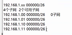
7.4.1.2 ??????
1.1.11100000.00000000
172.16.224
192~254
hostname Branch
!
interface GigabitEthernet0/0
ip address 172.16.159.254 255.255.240.0
ip access-group HQServer in
no shut
!
interface GigabitEthernet0/1
ip address 172.16.143.254 255.255.240.0
no shut
!
interface Serial0/0/0
ip address 192.168.0.2 255.255.255.252
no shut
!
router rip
version 2
passive-interface GigabitEthernet0/0
passive-interface GigabitEthernet0/1
network 172.16.0.0
network 192.168.0.0
no auto-summary
!
ip access-list standard HQServer
deny 172.16.128.0 0.0.31.255
permit any


hostname HQ
!
interface GigabitEthernet0/0
ip address 172.16.127.254 255.255.192.0
ip access-group BranchServer in
no shut
!
interface GigabitEthernet0/1
ip address 172.16.63.254 255.255.192.0
no shut
!
interface Serial0/0/0
ip address 192.168.0.1 255.255.255.252
no shut
!
interface Serial0/0/1
ip address 64.104.34.2 255.255.255.252
no shut
!
router rip
version 2
passive-interface GigabitEthernet0/0
passive-interface GigabitEthernet0/1
passive-interface Serial0/0/1
network 172.16.0.0
network 192.168.0.0
default-information originate
no auto-summary
!
ip route 0.0.0.0 0.0.0.0 Serial0/0/1
!
ip access-list standard BranchServer
deny 172.16.64.0 0.0.63.255
permit any
5/27
7.1.1.3 ACL
- 入站 ACL - 传入数据包经过处理之后才会被路由到出站接口。因为如果数据包被丢弃,就节省了执行路由查找的开销,所以入站 ACL 非常高效。如果 ACL 允许该数据包,则会处理该数据包以进行路由。当与入站接口连接的网络是需要检测的数据包的唯一来源时,最适合使用入站 ACL 来过滤数据包。(一进多出)
- 出站 ACL - 传入数据包路由到出站接口后,由出站 ACL 进行处理。在来自多个入站接口的数据包通过同一出站接口之前,对数据包应用相同过滤器时,最适合使用出站 ACL。(多进一出)
7.1.2.5
access-list 1 permit any
!OR
access-list 1 permit 0.0.0.0 255.255.255.255

access-list 1 permit 192.168.10.10 0.0.0.0
!OR
access-list 1 permit host 192.168.10.10
应用 ACL 的规则
一些使用 ACL 的指导原则:
-
在位于内部网络和外部网络(例如互联网)交界处的防火墙路由器上使用 ACL。
-
在位于网络两个部分交界处的路由器上使用 ACL,以控制进出内部网络特定部分的流量。
-
在边界路由器(即位于网络边界的路由器)上配置 ACL。这样可以在内外部网络之间,或网络中受控度较低的区域与敏感区域之间起到基本的缓冲作用。
-
为边界路由器接口上配置的每种网络协议配置 ACL。
为每种协议 (per protocol)、每个方向 (per direction)、每个接口 (per interface) 配置一个 ACL:
-
每种协议一个 ACL - 要控制接口上的流量,必须为接口上启用的每种协议定义相应的 ACL。
-
每个方向一个 ACL - 一个 ACL 只能控制接口上一个方向的流量。要控制入站流量和出站流量,必须分别定义两个 ACL。
-
每个接口一个 ACL - 一个 ACL 只能控制一个接口(例如 GigabitEthernet 0/0)上的流量。
7.1.4.1 拓展acl和标准的使用情况??
扩展 ACL - 将扩展 ACL 放置在尽可能靠近需要过滤的流量源的位置上。这样,不需要的流量会在靠近源网络的位置遭到拒绝,而无需通过网络基础设施。
标准 ACL - 由于标准 ACL 不会指定目标地址,所以其位置应该尽可能靠近目标。在流量源附近设置标准 ACL 可以有效阻止流量通过应用了 ACL 的接口到达任何其他网络。
标准 ACL 命令的完整语法如下:
Router(config)# access-list access-list-number { deny | permit | remark } source [ source-wildcard ] [ log ]
[ source-wildcard ] (可选)要应用到源得32位通配符掩码。在要忽略得位上置1。
7.2.1.2
配置标准 IPv4 ACL 之后,可以在接口配置模式下使用 ip access-group 命令将其关联到接口:
Router(config-if)# ip access-group { access-list-number | access-list-name } { in | out }
in/out 入站 出站过滤器
7.2.1.3
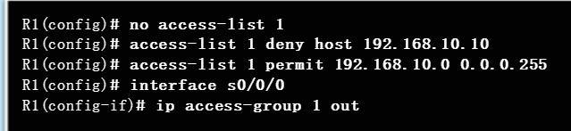
拒绝位于 192.168.10.10 的主机 PC1。但允许 192.168.10.0/24 网络中的其他各台主机。
7.2.2.3
show ip interface 端口
7.2.3.1
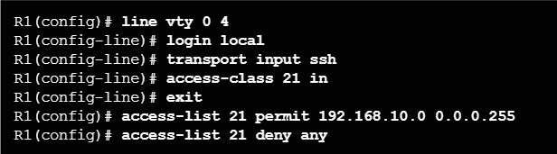
线路配置模式中配置的 access-class 命令可限制特定 VTY(接入思科设备)与访问列表中地址之间的传入和传出连接。
access-class 命令的语法是:
Router(config-line)# access-class access-list-number { in [ vrf-also ] | out }
==参数 in 限制访问列表中的地址和思科设备之间的传入连接,而参数 out 则限制特定思科设备与访问列表中地址之间的传出连接。==
7.3.1.2
思科 IOS 将应用内部逻辑。如前所述,ACE 是按照顺序处理的;因此,ACE 的输入顺序非常重要。
8.1.2.1 dhcp
要排除特定地址,请使用 ip dhcp excluded-address 命令。
ip dhcp pool 池名称 命令创建具有特定名称的地址池,并使路由器进入 DHCPv4 配置模式
必须配置地址池和默认网关路由器。使用 network 语句定义可用地址范围。
使用 default-router 命令定义默认网关路由器。通常,网关是最接近客户端设备的路由器的 LAN 接口。虽然只需要一个网关,但是如果有多个网关,您最多可以列出八个地址。
其他 DHCPv4 池命令为可选命令。例如,使用 dns-server 命令配置 DHCPv4 客户端可用的 DNS 服务器 IPv4 地址。domain-name domain 命令用于定义域名。使用 lease 命令可以更改 DHCPv4 租期。默认租用值为一天。netbios-name-server 命令用于定义 NetBIOS WINS 服务器。
要禁用此服务,请使用 no service dhcp 全局配置模式命令。使用 service dhcp 全局配置模式命令可重新启用 DHCPv4 服务器进程。如果没有配置参数,启用服务将不会有效果。
8.1.2.3 dhcp中继
如果将 R1 配置为 DHCPv4 中继代理,它会将请求转发至位于子网 192.168.11.0 的 DHCPv4 服务器。
R3(config)# interface g0/0
R3(config-if)# ip helper-address 192.168.11.6
7.2.1.6
R2(config)#access-list 1 deny 192.168.11.0 0.0.0.255
R2(config)#access-list 1 permit any

R3(config)#access-list 1 deny 192.168.10.0 0.0.0.255
R3(config)#access-list 1 permit any
R3(config-if)#int g0/0
R3(config-if)#ip access-group 1 out
7.2.1.7
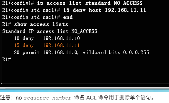
R1(config)#ip access-list standard File_Server_Restrictions
R1(config-std-nacl)#permit host 192.168.20.4
R1(config-std-nacl)#deny any
R1(config-if)#int f0/1
R1(config-if)#ip access-group File_Server_Restrictions out
7.2.3.3
Router(config)#access-list 99 permit host 10.0.0.1
Router(config)#line vty 0 15
Router(config-line)#access-class 99 i
8.1.3.3
R2(config)#ip dhcp excluded-address 192.168.10.1 192.168.10.10
R2(config)#ip dhcp excluded-address 19IP2.168.30.1 192.168.30.10

R2(config)#ip dhcp pool R1-LAN
R2(dhcp-config)#network 192.168.10.0 255.255.255.0
R2(dhcp-config)#default-router 10.1.1.2
R2(dhcp-config)#no default-router 10.1.1.2
R2(dhcp-config)#default-router 192.168.10.1
R2(dhcp-config)#dns-server 192.168.20.254

R2(config)#ip dhcp pool R3-LAN
R2(dhcp-config)#netw
R2(dhcp-config)#network 192.168.30.0 255.255.255.0
R2(dhcp-config)#dns
R2(dhcp-config)#dns-server 192.168.20.254
R2(dhcp-config)#def
R2(dhcp-config)#default-router 192.168.30.1


R1(config)#int g0/0
R1(config-if)#ip dh
R1(config-if)#ip he
R1(config-if)#ip help
R1(config-if)#ip helper-address 10.1.1.2

R3(config)#int g0/0
R3(config-if)#ip help
R3(config-if)#ip helper-address 10.2.2.2

//Step 1: Configure the Gigabit Ethernet 0/1 interface on R2 to receive IP addressing from DHCP and activate the interface.
R2(config)# interface g0/1
R2(config-if)# ip address dhcp
R2(config-if)# no shutdown
8.3.1.2
S2(config)#vlan 10
S2(config-vlan)#name Sales
S2(config-vlan)#vlan 20
S2(config-vlan)#name Production
S2(config-vlan)#vlan 30
S2(config-vlan)#name Marketing
S2(config-vlan)#vlan 40
S2(config-vlan)#name HR
S2(config-vlan)#ex
S2(config)#int rang
S2(config)#int range f0/5-9
S2(config-if-range)#sw m ac
S2(config-if-range)#sw ac vlan 10
S2(config-if-range)#int range f0/10-14
S2(config-if-range)#sw m ac
S2(config-if-range)#sw ac vlan 20
S2(config-if-range)#int range f0/15-19
S2(config-if-range)#sw m ac
S2(config-if-range)#sw ac vlan 30
S2(config-if-range)#int range f0/20-24
S2(config-if-range)#sw m ac
S2(config-if-range)#sw ac vlan 40

S2(config)#int f0/1
S2(config-if)#sw m trunk
S2(config-if)#int f0/2
S2(config-if)#sw m trunk
S2(config-if)#int f0/3
S2(config-if)#sw m trunk
S2(config-if)#int f0/4
S2(config-if)#sw m trunk

R1(config)#int g0/0.10
R1(config-subif)#encapsulation dot1Q 10
R1(config-subif)#ip add 172.31.10.1 255.255.255.224
R1(config-subif)#int g0/0.20
R1(config-subif)#encapsulation dot1Q 20
R1(config-subif)#ip add 172.31.20.1 255.255.255.240
R1(config-subif)#int g0/0.30
R1(config-subif)#encapsulation dot1Q 30
R1(config-subif)#ip add 172.31.30.1 255.255.255.128
R1(config-subif)#int g0/0.40
R1(config-subif)#encapsulation dot1Q 40
R1(config-subif)#ip add 172.31.40.1 255.255.255.192

R1(config)#ip dhcp pool VLAN_10
R1(dhcp-config)#dns-server 209.165.201.14
R1(dhcp-config)#default-router 172.31.10.1
R1(dhcp-config)#network 172.31.10.0 255.255.255.224
R1(config)#ip dhcp pool VLAN_20
R1(dhcp-config)#dns-server 209.165.201.14
R1(dhcp-config)#network 172.31.20.0 255.255.255.240
R1(dhcp-config)#default-router 172.31.20.1
R1(config)#ip dhcp pool VLAN_30
R1(dhcp-config)#network 172.31.30.1 255.255.255.128
R1(dhcp-config)#dns-server 209.165.201.14
R1(dhcp-config)#default-router 172.31.30.1


R1(config)#ip dhcp excluded-address 172.31.10.1 172.31.10.10
R1(config)#ip dhcp excluded-address 172.31.20.1 172.31.20.10
R1(config)#ip dhcp excluded-address 172.31.30.1 172.31.30.10
R1(config)#ip dhcp excluded-address 172.31.40.1 172.31.40.10
第九章
9.1.2.1 静态nat
NAT 转换有三种类型:
-
静态地址转换(静态 NAT)- 本地地址和全局地址之间的一对一地址映射。
-
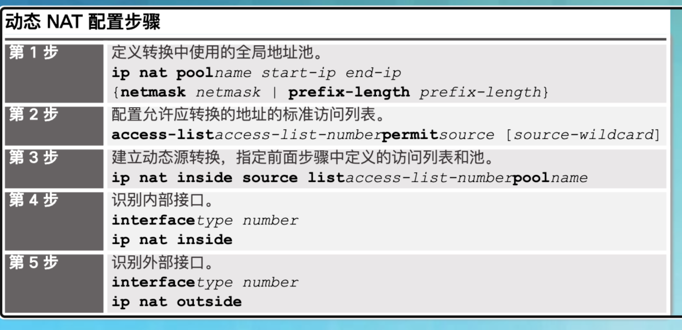
动态地址转换(动态 NAT)- 本地地址和全局地址之间的多对多地址映射。转换在可用的基础上进行:例如,如果有 100 个内部本地地址和 10 个内部全局地址,则任何时候都只能转换 100 个内部本地地址中的 10 个地址。动态 NAT 的这种限制使得它在用于生产网络时没有端口地址转换那么实用。
-
端口地址转换 (PAT) - 本地地址和全局地址之间的多对一地址映射。此方法也称为过载(NAT 过载)。例如,如果有 100 个内部本地地址以及 10 个内部全局地址,PAT 使用端口作为附加参数来提供乘数效应,从而支持重复使用 10 个内部全局地址中的任何一个地址,重复次数高达 65,536 次(这取决于通信流是基于 UDP、TCP 还是 ICMP)。
show ip nat translations。
9.2.1.4
Ip nat inside static Inside_local_IP_address Inside_global_IP_address
Ip nat inside static Outside_global_IP_address Outside_local_IP_address
R1(config)#ip nat inside source static 172.16.16.1 64.100.50.1
R1(config)#ip nat outside source static 64.100.50.1 209.165.128.130
(config)#int g0/0
R1(config-if)#ip nat inside
R1(config-if)#int s0/0/0
R1(config-if)#ip nat outside
9.2.2.2 配置动态nat
9.2.2.5
R2(config)#access-list 1 permit 172.16.0.0 0.0.255.255
R2(config)#ip nat pool DYNAMIC 209.165.76.196 209.165.76.199 netmask 255.255.255.
// Associate ACL1 with the NAT pool.
R2(config)#ip nat inside source list 1 pool DYNAMIC
R2(config)# interface s0/0/0
R2(config-if)# ip nat outside
R2(config-if)# interface s0/0/1
R2(config-if)# ip nat inside
9.2.3.1 配置PAT:地址池
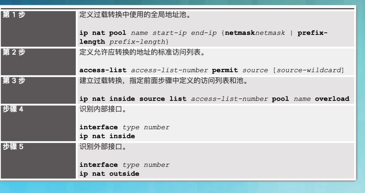
overload 关键字会启用 PAT。
9.2.3.6
R2(config)# ip access-list standard R2NAT
R2(config-std-nacl)# permit 192.168.10.0 0.0.0.255
R2(config-std-nacl)# permit 192.168.20.0 0.0.0.255
R2(config-std-nacl)# permit 192.168.30.0 0.0.0.255

//使用名为 R2POOL 的 NAT 池配置 R2,该 NAT 池使用 209.165.202.128/30 地址空间中的第一个地址。
R2(config)# ip nat pool R2POOL 209.165.202.129 209.165.202.129 netmask 255.255.255.
//将命名 ACL 与 NAT 池相关联,并启用 PAT。
R2(config)# ip nat inside source list R2NAT pool R2POOL overload

//使用相应的内部和外部 NAT 命令配置 R2 接口。
R2(config)# inte fa0/0
R2(config-if)# ip nat inside
R2(config-if)# inte s0/0/0
R2(config-if)# ip nat inside
R2(config-if)# inte s0/0/1
R2(config-if)# ip nat inside
R2(config-if)# inte s0/1/0
R2(config-if)# ip nat outside

//请参考拓扑结构。 创建静态 NAT 转换,以将 local.pka 内部地址映射至其外部地址
R2(config)# ip nat inside source static 192.168.20.254 209.165.202.130
9.3.1.4
//Correct the Interfaces.
//Assign the ip nat inside and ip nat outside commands to the correct ports.

R2(config)# interface Serial0/0/0
R2(config-if)# ip nat outside
R2(config-if)# interface Serial0/0/1
R2(config-if)# ip nat inside

//Correct the Access-list.
//Delete access-list 101 and replace it with a similar list that is also one statement in length. The only difference should be the wildcard.

R2(config)# no access-list 101
R2(config)# access-list 101 permit ip 10.4.10.0 0.0.1.255 any
9.4.1.2
Switch(config)#host HQ-SW
HQ-SW(config)#ip domain-name cisco.com
HQ-SW(config)#crypto key generate rsa
How many bits in the modulus [512]: 1024
HQ-SW(config)#username HQadmin password ciscoclass
HQ-SW(config)#ip ssh version 2
HQ-SW(config)#ip ssh authentication-retries 2
HQ-SW(config)#ip ssh time-out
HQ-SW(config)#line vty 0 15
HQ-SW(config-line)#login local
HQ-SW(config-line)#transport input ssh
HQ-SW(config)#service password-encryption
考题记录
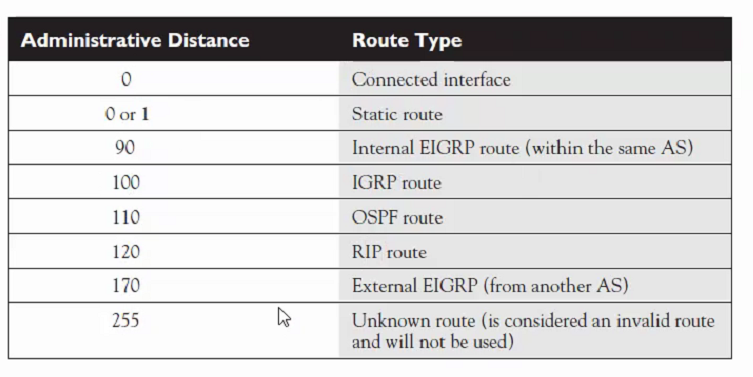
ospf管理距离为110
DNS 53端口 即是UDP也是TCP
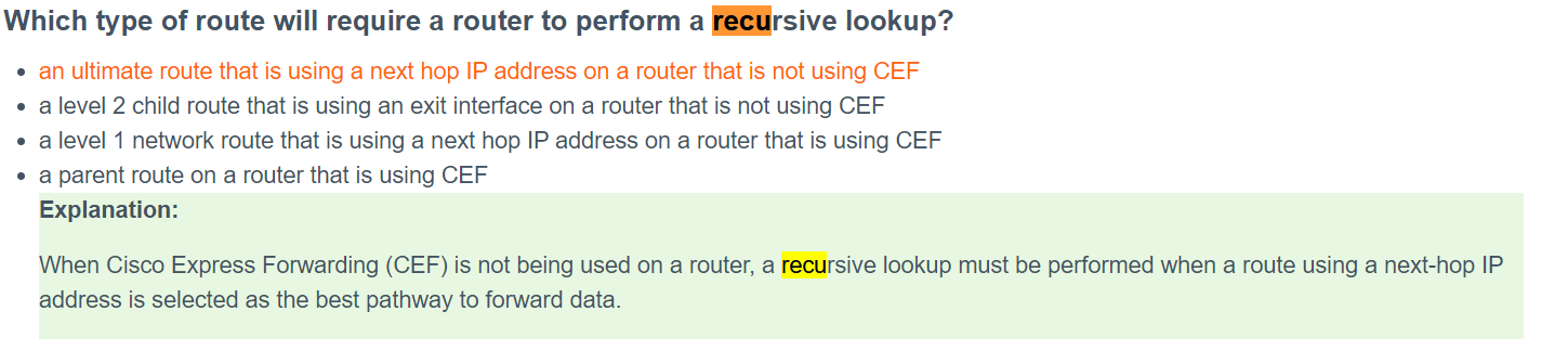
What happens to a static route entry in a routing table when the outgoing interface is not available? The route is removed from the table.
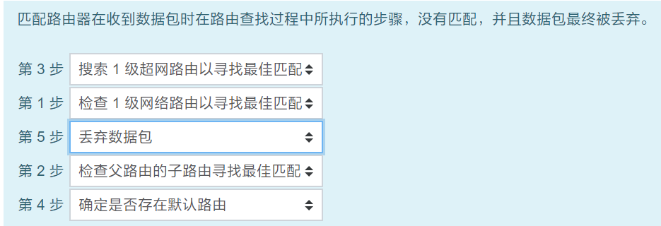
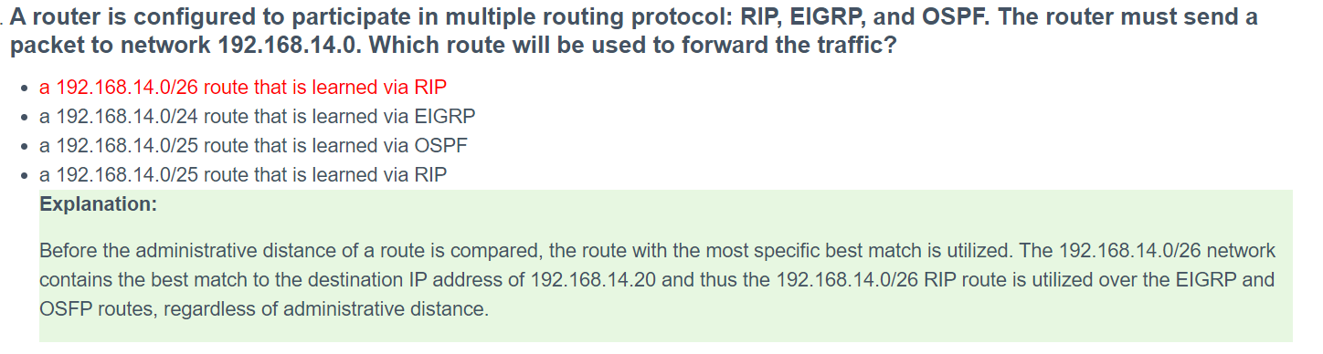
匹配最长

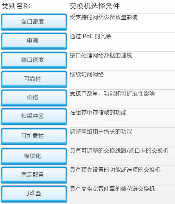
模块化交换机通过使用线路卡提供了容错和带宽可用性与将来扩展的功能,但实施成本非常昂贵。堆叠式交换机通过在交换机之间使用特殊电缆提供容错和带宽可用性,并且比模块化交换机的实施成本低。非堆叠式交换机不提供这些功能。固定配置交换机是不支持自带功能以外功能的单个交换机。
交换机分层设计模型有哪三层?
接入层是最低层,它为用户提供网络访问。分布层具有很多功能,但是它聚合接入层的数据,提供过滤、策略控制并设置第 3 层路由边界。核心层提供高速连接。
为提高效率、可扩展性和成本效益,建议建立从一个中心站点到所有其他园区站点的扩展星型拓扑。网状拓扑更昂贵,总线和双环拓扑更难进行故障排除和维护。
网络设计师何时会关注 RU?
何时考虑端口密度 何时计算最大端口速度 何时确定可用的线卡数量 何时购买用于网络机架的特定数量的交换机
机架单元或 RU 是与交换机高度相关的一项特定测量。1 RU 交换机的额定值小于 2 RU 交换机的额定值。端口密度测量交换机上的端口数。模块化影响可用线卡的数量。端口速度测量可流过给定端口的每秒比特数。
正确答案是:何时购买用于网络机架的特定数量的交换机
融合网络中的自动话务员功能提供什么服务?
点对点视频 呼叫路由 IT 管理接口 视频会议
自动话务员功能通过将呼叫直接路由到个人或部门,从而加快语音服务的速度。点对点视频和视频会议说明了融合网络中的视频服务。IT 管理接口是融合网络解决方案的一部分,能够让 IT 人员通过统一应用执行移动、添加和更改等操作。
正确答案是:呼叫路由
哪两个特征描述了融合网络?(请选择两项。)
降低了服务呼叫 使用相同的交换机支持语音和视频 语音和视频流量的单独布线基础设施 中小型企业的可负担性 更低的设备成本
融合网络具有传统的用户流量以及数字化语音和视频流量,这些流量以前需要单独的网络。现在,不再是单独的组管理单独的网络,一组人员即可管理网络。
正确答案是:使用相同的交换机支持语音和视频, 中小型企业的可负担性
What type of network uses one common infrastructure to carry voice, data, and video signals?
-
switched
-
borderless
-
converged
-
managed
**Explanation:**A converged network has only one physical network to install and manage. This results in substantial savings over the installation and management of separate voice, video, and data networks.
Which solution would help a college alleviate network congestion due to collisions?
-
a firewall that connects to two Internet providers
-
a high port density switch
-
a router with two Ethernet ports
-
a router with three Ethernet ports
**Explanation:**Switches provide microsegmentation so that one device does not compete for the same Ethernet network bandwidth with another network device, thus practically eliminating collisions. A high port density switch provides very fast connectivity for many devices.
alleviate:减轻
congestion:拥塞
collisions:碰撞
What is a basic function of the Cisco Borderless Architecture distribution layer?
-
acting as a backbone
-
aggregating all the campus blocks
-
aggregating Layer 3 routing boundaries
-
providing access to end user devices
**Explanation:**One of the basic functions of the distribution layer of the Cisco Borderless Architecture is to perform routing between different VLANs. Acting as a backbone and aggregating campus blocks are functions of the core layer. Providing access to end user devices is a function of the access layer.
A network designer must provide a rationale to a customer for a design which will move an enterprise from a flat network topology to a hierarchical network topology. Which two features of the hierarchical design make it the better choice? (Choose two.)
-
lower bandwidth requirements
-
reduced cost for equipment and user training
-
easier to provide redundant links to ensure higher availability
-
less required equipment to provide the same performance levels
-
simpler deployment for additional switch equipment
**Explanation:**A hierarchical design for switches helps network administrators when planning and deploying a network expansion, performing fault isolation when a problem occurs, and providing resiliency when traffic levels are high. A good hierarchical design has redundancy when it can be afforded so that one switch does not cause all networks to be down.
What does the term “port density” represent for an Ethernet switch?
-
the memory space that is allocated to each switch port
-
the number of available ports
-
the numbers of hosts that are connected to each switch port
-
the speed of each port
**Explanation:**The term port density represents the number of ports available in a switch. A one rack unit access switch can have up to 48 ports. Larger switches may support hundreds of ports.
What is a definition of a two-tier LAN network design?
-
access and core layers collapsed into one tier, and the distribution layer on a separate tier
-
access and distribution layers collapsed into one tier, and the core layer on a separate tier
-
distribution and core layers collapsed into one tier, and the access layer on a separate tier
-
access, distribution, and core layers collapsed into one tier, with a separate backbone layer
**Explanation:**Maintaining three separate network tiers is not always required or cost-efficient. All network designs require an access layer, but a two-tier design can collapse the distribution and core layers into one layer to serve the needs of a small location with few users.
What are two reasons a network administrator would segment a network with a Layer 2 switch? (Choose two.)
-
to create fewer collision domains
-
to enhance user bandwidth
-
to create more broadcast domains
-
to eliminate virtual circuits
-
to isolate traffic between segments
-
to isolate ARP request messages from the rest of the network
**Explanation:**A switch has the ability of creating temporary point-to-point connections between the directly-attached transmitting and receiving network devices. The two devices have full-bandwidth full-duplex connectivity during the transmission.
A collapsed core design is appropriate for a small, single building business. This type of design uses two layers (the collapsed core and distribution layers consolidated into one layer and the access layer). Larger businesses use the traditional three-tier switch design model
Which statement describes a result after multiple Cisco LAN switches are interconnected?
-
The broadcast domain expands to all switches.
-
One collision domain exists per switch.
-
Frame collisions increase on the segments connecting the switches.
-
There is one broadcast domain and one collision domain per switch.
**Explanation:**In Cisco LAN switches, the microsegmentation makes it possible for each port to represent a separate segment and thus each switch port represents a separate collision domain. This fact will not change when multiple switches are interconnected. However, LAN switches do not filter broadcast frames. A broadcast frame is flooded to all ports. Interconnected switches form one big broadcast domain.
What are two advantages of modular switches over fixed-configuration switches? (Choose two.)
-
lower cost per switch
-
increased scalability
-
lower forwarding rates
-
need for fewer power outlets
-
availability of multiple ports for bandwidth aggregation
**Explanation:**Fixed-configuration switches, although lower in price, have a designated number of ports and no ability to add ports. They also typically provide fewer high-speed ports. In order to scale switching on a network that consists of fixed-configuration switches, more switches need to be purchased. This increases the number of power outlets that need to be used. Modular switches can be scaled simply by purchasing additional line cards. Bandwidth aggregation is also easier, because the backplane of the chassis can provide the bandwidth that is needed for the switch port line cards.
What two criteria are used by a Cisco LAN switch to decide how to forward Ethernet frames? (Choose two.)
-
path cost
-
egress port
-
ingress port
-
destination IP address
-
destination MAC address
**Explanation:**Cisco LAN switches use the MAC address table to make decisions of traffic forwarding. The decisions are based on the ingress port and the destination MAC address of the frame. The ingress port information is important because it carries the VLAN to which the port belongs.
What is one function of a Layer 2 switch?
-
forwards data based on logical addressing
-
duplicates the electrical signal of each frame to every port
-
learns the port assigned to a host by examining the destination MAC address
-
determines which interface is used to forward a frame based on the destination MAC address
**Explanation:**A switch builds a MAC address table of MAC addresses and associated port numbers by examining the source MAC address found in inbound frames. To forward a frame onward, the switch examines the destination MAC address, looks in the MAC address for a port number associated with that destination MAC address, and sends it to the specific port. If the destination MAC address is not in the table, the switch forwards the frame out all ports except the inbound port that originated the frame.
Which network device can be used to eliminate collisions on an Ethernet network?
-
firewall
-
hub
-
router
-
switch
**Explanation:**A switch provides microsegmentation so that no other device competes for the same Ethernet network bandwidth.
What is the destination address in the header of a broadcast frame?
FF-FF-FF-FF-FF-FF
A converged network provides a single infrastructure that combines voice, video, and data. Analog phones, user data, and point-to-point video traffic are all contained within the single network infrastructure of a converged network.
打开交换机时,启动顺序中的第一个操作是什么?
A. 加载默认 Cisco IOS 软件
B. 加载启动加载器软件
C. 低级 CPU 初始化
D. 加载加电自检程序
答案
D. 交换机启动后的第一个操作是 POST(加电自检)。POST 对 CPU、内存和闪存进行测试,以准备加载启动加载器。
网络管理员配置了 VLAN 99 作为管理 VLAN,并为其配置 IP 地址和子网掩码。管理员发出 show interface vlan 99 命令并注意到线路协议处于关闭状态。以下哪项操作可以将线路协议的状态更改为开启?
A. 将主机连接到与 VLAN 99 相关联的接口
B. 配置默认网关
C. 从 VLAN 99 中删除所有接入端口
D. 在 vty 线路上配置传输输入法
答案
A. 一旦 SVI 配置了 IP 地址和子网掩码,即可用于远程管理。当 SVI VLAN 有一个活动端口与之关联时,SVI 接口处于活动状态。
攻击者已经绕过物理安全并且可以将笔记本电脑连接到交换机上的以太网接口。如果所有交换机端口都配置了端口安全,并且违规模式设置为出厂默认设置,则针对攻击者采取哪项操作?
A. 具有未知源地址的数据包被丢弃,并且没有已发生安全违规的通知。。
B. 具有未知源地址的数据包被丢弃,并且有已发生安全违规的通知。
C. 具有未知源地址的数据包被丢弃,并且接口进入错误禁用状态并关闭端口 LED。
D. 具有未知源地址的数据包被转发,并且会向 syslog 服务器发送通知。
答案
C. 默认违规模式已关闭。在此模式下,端口安全违规将造成接口立即变为错误禁用 (error-disabled) 状态,并关闭端口 LED。该模式还会发送 SNMP 陷阱、将 syslog 消息记入日志,以及逐渐增加违规计数器的计数。
似乎是交换机的默认配置。
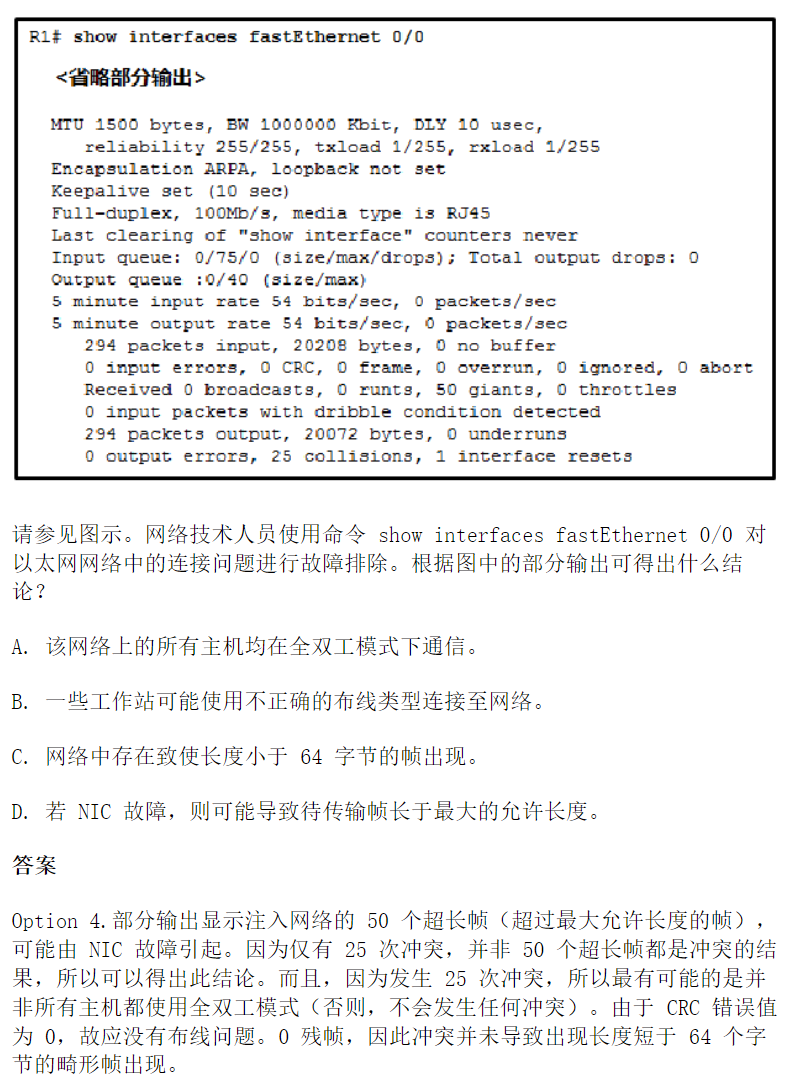
使用交换机时,造成不完全以太网帧的潜在原因是什么?
A. 双工配置错误
B. 线缆过长
C. 延迟冲突
D. NIC 故障
答案
D. 不完全帧即小于 64 字节的帧,所允许的最小值是以太帧。该类型帧通常是由于 NIC 故障或过度冲突。两端配置错误可能导致连接问题。线缆过长可能产生 CRC 错误和/或延迟冲突。
端口速度 LED - 表示选择了端口速度模式。 选择后,端口 LED 将显示不同含义的颜色。 如果 LED 不亮,则端口运行速度为 10 Mb/s。 如果 LED 为绿色,则端口运行速度为 100 Mb/s。 如果 LED 为绿色闪烁,则端口运行速度为 1000 Mb/s。
下列哪项操作可以将错误禁用交换机端口返回至运行状态?
A. 在接口上删除并重新配置端口安全
B. 在接口上发出 switchport mode access 命令
C. 清除交换机上的 MAC 地址表
D. 发出 shutdown 和 no shutdown 接口命令
答案
Option 4. 当配置了端口安全的交换机端口出现违规时会将违规操作关闭,端口将置为 err-disabled 状态。可以通过关闭接口然后发出 no shutdown 命令重新启用接口。
交换机引导加载程序的功能是什么?
A. 加快引导过程
B. 提供交换机启动时的脆弱状态安全
C. 控制启动过程中交换机的可用 RAM 量
D. 提供无法找到交换机操作系统时的操作环境
答案
Option 4 在交换机找不到有效操作系统时,显示交换机启动加载程序环境。启动加载程序环境提供一些基本命令来允许网络管理员重新加载操作系统或者提供操作系统的备选位置。
哪一命令用于设置定义交换机上 IOS 映像查找位置的 BOOT 环境变量?
- boot system
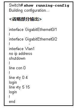
哪个接口是包含用于管理 24 个端口以太网交换机的 IP 地址的默认位置?
- VLAN 1
「真诚赞赏,手留余香」
 Mr.Be1ieVe's Treasure
真诚赞赏,手留余香
使用微信扫描二维码完成支付